Blog:
Battery Management Systems
Welcome to this blog post which provides a broad overview of the application of lithium-ion batteries in embedded systems. This post is the second of a 4-part series. For part 1, please see here.
As we have seen, we have to control, protect, and charge our battery pack with some intelligent system on the carrier board. There should be current and voltage protection. We wish to keep track of the exact voltage level of each battery cell of the pack, at any time. If we have a serial configuration, we need a balancing system, which keeps the cells on the same voltage level. Together with a charging circuit, all these elements build a battery management system. There are thousands of possible solutions from different manufacturers. Some devices integrate several functions, so the parts have to be chosen carefully. Here in this part, I provide you with some useful links as a good starting point to possible solutions - of course, there are more providers than those in this small list.
http://www.ti.com/power-management/battery-management/overview.html
http://www.analog.com/en/products/power-management/battery-management.html
https://www.richtek.com/battery-management/en/index.html
https://www.renesas.com/in/en/products/power-management/battery-management-system-tutorial.html
https://www.maximintegrated.com/en/products/power/battery-management.html
http://www.lapis-semi.com/en/semicon/monitor/index.html
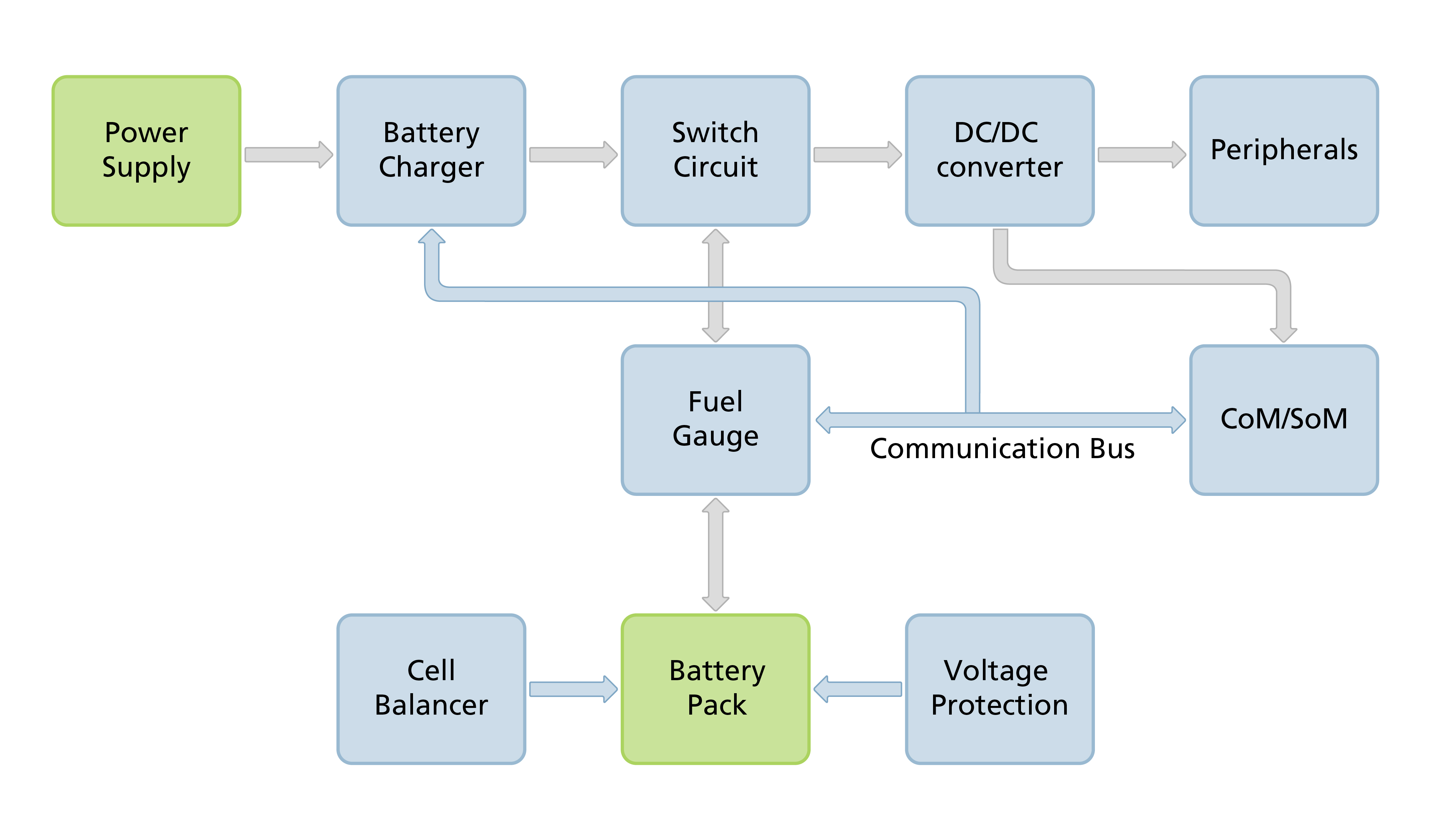
It’s more important to understand the systematic approach. That’s why we now have a look at the general block diagram:

Let us start with the normal operation mode. The Computer on Module (CoM) and the peripherals on the carrier board are supplied by the battery pack. The battery pack has a voltage protection and cell balancer. It depends on your battery pack if these elements are already integrated or not. If you use e.g. a 2S1P configuration with discrete cells, these functionalities should be implemented on the carrier board. The fuel gauge measures the current and battery voltage. By counting the charge (coulomb) it can determine the actual state of charge. The voltage regulator ensures that the board circuits are supplied with the exact voltage required and are not affected by the voltage changes of the battery. The converter should have at least the same voltage input range as the battery voltage range. Let us think about some important points. Depending on the battery voltage the topology can be a buck, boost or even a buck-boost converter. The converter should be designed for the required current and has low power losses. It is important that in standby mode the power consumption is very low, otherwise the battery will be discharged too much over time.
How do we charge our system? An external power supply is used to charge the battery. We have to provide the CC/CV charging method for this we need a battery charger solution. To enable charging with a constant current, the charger solution has to provide a higher charging voltage than the present battery voltage. Simplified, that is nothing else than a more intelligent voltage regulator. The design questions remain the same about input and output voltage, current, power losses and topology. Let’s take an example: a 2S battery pack needs to be charged with a 9 or 12-volt external power supply. The battery charger only has to be in a buck converter topology. If we assume that we only need a 3.3-volt power supply for our peripherals and System on Chip, then again only one voltage regulator in buck topology with the input voltage of 5 to 8.4 volts is needed. I suggest using a 2S configuration for an embedded system, which requires usually 3.3 and 5 volts. A second DC/DC converter can be used to generate 5 volts. Using only one cell is more difficult, as it needs a buck-boost converter for the system. I recommend using only one defined power supply in order to have a simple charger IC. But at the end, it depends only on your application! It gets a little bit complicated when your marketing team wants to have charging possibilities over USB. I will try and cover this requirement in the next part.
In our simplified general battery management system, you can find switch circuits between battery, charger and DC/DC converters. The need for such a switch depends on whether you want to disconnect the fully charged battery from the external supply or not, while the embedded system is still running. I recommend disconnecting the battery from the embedded system and external supply after charging to not stress the battery additionally. The communication between System on Module (SoM) and charger IC is to determine all kinds of status or settings. Of course, I am not covering all kinds of battery management systems with this blog post. For example, a common variation of this architecture is that some parts of the battery circuits are part of the battery pack already. In this case, the battery packs provide normal communication interfaces.
I hope that I was able to explain the basic battery management elements in order to give you an easy overview. Now it should be easier to go through the links above and look for a suitable solution for your design. In part 4 of this blog series, I will present a possible BMS solution, which can be updated and adapted to your needs.